Wednesday 19 June 2013

Prototype pictures - Bagger 288


Prototype at work
Main crawlers on prototype

A slight accident with a bulldozer - see yellow bulldozer on top of wheel!
Close view of a bucket

Crossing road to new mine

Meccano model: selection of pictures

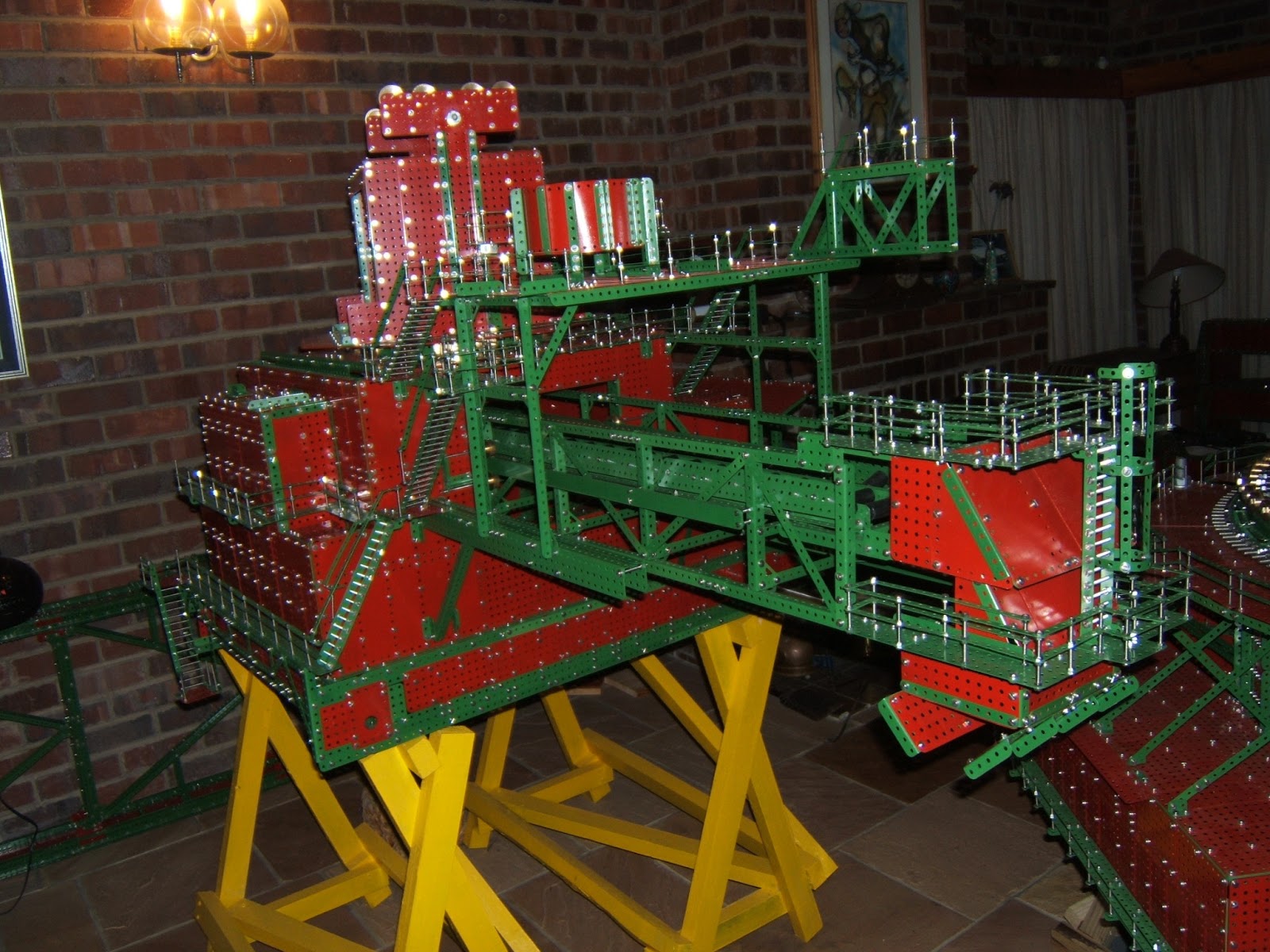
12crawler track frames and 3 support bridges


19 foot delivery arm
More work on the auxiliary unit


More work done on auxiliary unit
Winding drums and service crane
14.5 foot bucket wheel arm


Bucket wheel - note protective box for its motors


Driver's cab on bucket wheel arm


Delivery arm

Tuesday 18 June 2013

Motorisation of the model


I have acquired a 1000 watt transformer/rectifier unit with cooling fan (as shown above), made by Postma and Postma of Port Elizabeth.  Output current is 83 amps at 12 volts (12 x 83 = 996).  Steve Craigie (my electrician) and I tested a single window winder for current drawn.  This was1.8 amps (no load) and 3.5 amps (maximum load).  The 83 amp output will allow the whole model to move – that is, 15 motors.  One should also be able to run the conveyor belts at the same time as their load is very light (10 motors).

I have also done much work on the gearing systems for the motorisation.  All gears and brass fittings have been made.  On the board shown below are about half the total large-tooth gears needed.  In the photograph are two gear clusters, each consisting of a pinion and a gear wheel joined by means of a brass spacer and four 3mm bolts, with nuts.


This allows transfers of very large torques in the reduction gear boxes without the risk of grub screws tearing loose on the axles, which would certainly happen at the high torque needed to move a model of this weight.  I calculate that the final drive wheels in the crawler tracks will rotate at just under 1 rpm.  This gives a linear speed of about 350mm per minute. 


Final drive wheel/gear assembly


Final drive wheel/gear assembly

Components of final drive wheel/gear assembly.

 In the photographs is a final drive wheel/gear assembly.  In the third photo are components of this assembly: two 115mm nylon wheels of 8mm gauge, two 4" face plates (2mm gauge versions of the Meccano face plate), two aluminium spacers with Meccano’s familiar octet of holes and a 48 tooth gear wheel (2mm steel). Eight 65mm stainless steel screws hold the cluster together through the central octet of holes while the nylon wheels each have an octet of countersunk screws fixing them to the heavy face plate.  Countersinking was necessary because clearances between wheels and the crawler track frames are tight. 

To drill the holes in the gears and pinions accurately I have had another drilling jig made by Derek of K.V. Precision Engineering of Uitenhage.  This is shown in the below photograph.

Drilling jig
As you can see it is a beautifully-made tool.  With this I can drill up to 3 concentric octets of standard Meccano holes as well as a small radius quartet of 3mm holes which I use to create the clustered gear wheel/pinion sets shown earlier.  3mm screws were necessary in order to avoid hitting the 8mm shafts or the teeth of the small pinions.


Counterbalance arm

The counterbalance arm has now been completed.  This is bolted to the central triangular frame by means of 10mm stainless steel bolts, since the angles which upper and lower chords make with the vertical are not 90° (and are different in each case). This would make a joint with multiple 4mm bolts very difficult unless one drilled a lot of non-standard holes (I reckoned a single non-standard bolt was better than this).  These 10 mm bolts fix into deeply embedded straps on either side (the two units being joined, that is).

At the far end of the counterbalance arm the two winding drums can be seen.


Each drum is driven by two window winder motors meshing directly onto the drum’s 8", 99 (large) tooth gear wheel as seen.  These drums are now motorised and revolve at about 7 rpm.  Also visible in the photograph is a servicing crane for the winding drum area, motorised by three meccano 6 volt motors, one each for slewing, elevation and hook position.

Servicing crane for the winding drum area


Workshop/store building
Just behind the triangular frame is a large workshop/store building 5 foot by 18½" by 7½". The floor of this structure is formed from 2 large plates (which were once the sides of an old electric stove which I scrapped!).  The side are largely flexible plate made from recycled spray paint cans.  It is therefore quite light, but pretty rigid.

Note the extensive use of compound girders in the mainframe structure. These are slightly heavier than those used in the bucket-wheel arm (some 1" flat girders being replaced by 1½" ones).  This follows the prototype.  The reason is that distances between main joint knuckles are quite a bit larger than in the bucket-wheel case and, according to Euler’s theory of buckling, the tendency to buckle goes up with the square of this distance.