A video clip (about 6 minutes) of
the model
has now been made
(by Neil Shaw, an independent film-maker from
Cape Town) showing the various motorisations working (traversing back and
forth, slewing of upper arms, raising and lowering of bucket when arm rotation
of bucket wheel, and all 6 conveyor belts running (including static conveyor of
20 foot).
All the minor movements
(accuated with a total of sixteen 6 volt Meccano motors) are also featured (5
service cranes, and up and down movement of front driver’s cabs).
This clip is now owned by AP (Associated
Press) and will be sold to about 300 TV stations worldwide.
These stations then have the right to edit
the clip for their own use.
A short version (about 1 minute) has already appeared on YouTube.
I am happy to say that the final
assembly went well with no mishaps.
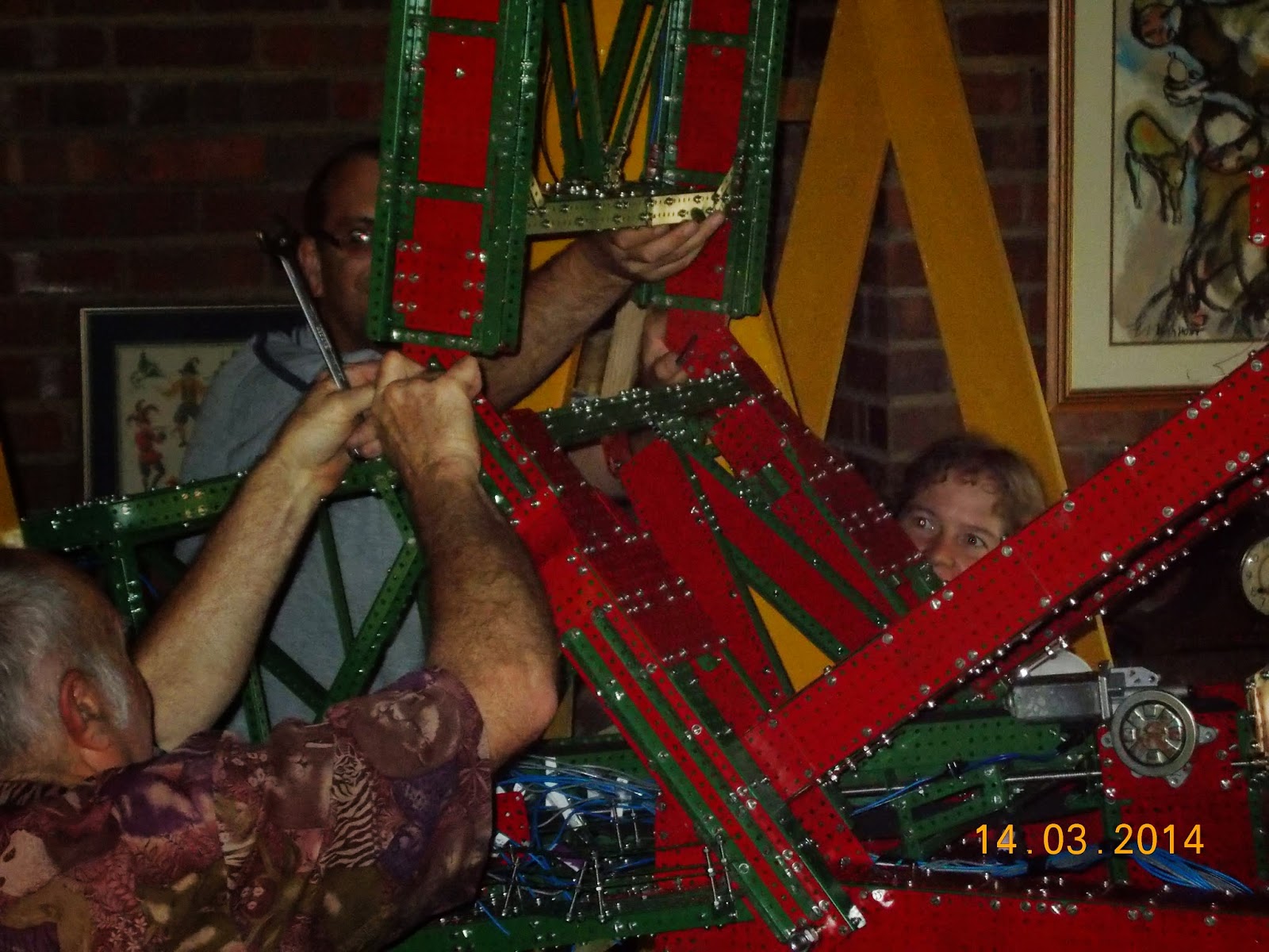
Stage one was to lift the central unit onto its crawler system. This was done as follows: first the wooden lifting cradle was attached
to the three upper protruding M20 bolts which go down into the crawler bridge
units. This was then lifted (by 8
people, as the combined unit now weighed over 240kg) onto two strong A-frames,
which in turn rested on eight stacks of 2-high bricks. This allowed enough room under the M20 bolts
to slip the bridges on from underneath and to bolt up with M20 locknuts from
below (once three 65mm diameter brass spacers had been slipped into place, to
get the correct distance between bridges and vertical finlike structures on the
outside of the main unit.) These brass fittings had cuplike voids machined out
on one side to accommodate the locknuts.
This ensured that flat surfaces on the bridges remained parallel with
flat surfaces below the fins. This had
the effect of helping to keep the bridges from buckling forward or backward. Of
course, for such buckling to occur, the M20 bolts would have to bend quite
seriously. This is not likely, as they are high tensile.
At this stage the whole structure
had to be lifted by the 8 lifters and held while the bricks were removed from
under the A-frames, a rather tense interval.
When the cradle was replaced on the A-frames there was just enough room
to slide the twelve main crawler units sideways onto their M20 rocker axles
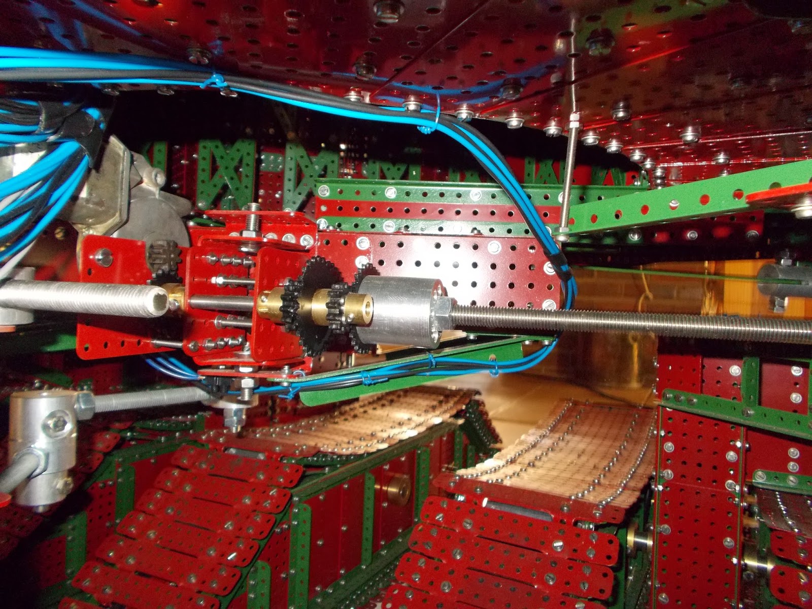
protruding from the bridges. Large brass
collars then locked them securely in place.
With the crawlers and bridges
securely in place the whole central unit weighed more than 500kg. This was too heavy for even for 8 lifters so
the final downward trip of about 1 inch was done using my 2-ton hydraulic car
jack and some supporting timber, first at one end of the cradle and then the
other. For the first time the central
unit was on its “feet” and mobile. The
24 cores to the 12 motors were connected to a 12 volt source and the crawler
system and found to be satisfactory (before the final lowering onto the ground
I had been very careful to check all motor polarities – to have one motor
trying to work against the other 11 would be very rough on the works!)
The next big task for the lifting
team was performed a week later and involved fixing the main horizontal arms in
place. First the rotating upper toroidal
ring had been put in place on its roller race of 65 brass flanged wheels. A set of 6 locking flanged wheels had been
put in place on three strong vertical arms which came up the inside of the
upper torus. These wheels roll on
another roller race on the top of the upper torus. Their purpose is to prevent the whole upper
machine from toppling over, should any unforeseen accident occur (the machine will
sit on a vertical surface for its lifetime and is well-balanced even if slight
tipping happens, having a low centre of gravity in relation to the main
support).
The first arm to be attached was
the counterbalance. This had already been bolted to the heavy central
triangular frame of box girders by means of four M10 bolts into heavy straps
(rather than multiple M4 bolts, since the angles were not 90°, as explained elsewhere). My helpers carried the 140 kg arm over and
lifted it into place on some wooden scaffolds (since the winding drum end
needed to be over 8 feet off the ground.
There were some anxious moments
for me as the four 12mm holes drilled on the bottom of the box girder frame
came down on four M12 bolts protruding from the upper ring. This match had not been tested before, as the
separate parts were too heavy for me to move around on my own. Fortunately the fit was good. I must admit that I had a 14mm drill bit on
standby on my portable drill in case I had to ream a 12mm hole out to 14mm!
Once the counterbalance arm had
been bolted in position the bucket wheel arm could be brought over and two M12
bolts slipped into place to act as pivots on which this arm can move (to change
the height of digging wheel). Again, the fit had not been tested, due to the
enormous weight, but all went together smoothly. Several of the bolts in critical places on
the two components had been replaced by countersunk bolts (into 2mm plate) to
avoid bolthead clash as the bucket wheel arm moved. This turned out to be a wise move. So ended the day’s work with the horizontal
arms resting on trestles at their outer ends.
The next main stage was the upright
arm placement. To be safely accomplished
this required some serious scaffolding.
I had made the components ahead of time and now they needed to be
erected: two 9 foot high scaffolds were built, one on either side of the model,
during the next 2 weeks.
On the day of the fitment my
helpers passed each 45kg upright arm up handlers sitting on top of the 9 foot
scaffolds. From there they were lowered and M10 bolts put through lugs on the
arms and on the waiting model below. All went well except I put an upright on
back to front! It had to be turned around and re-bolted. At this stage the
upright arms were held in place by wooden struts bridging the gap between
scaffolds.
Over the next week or so the 2mm
braided steel wires were run onto the large winding drums and around the
thirty-four 4 inch aluminium pulleys atop the two upright arms. The fixed length 8mm threaded rods were
slipped into their retaining blocks and lock-nutted. The winding drums were then started and the
cables brought into tension so that the whole model became
self-supporting. By trial and error it
was determined that the balance of the model was optimum when 35kg of concrete
blocks were placed under the winding drum area.
All motions could now be tested:
traversing, slewing, raising and lowering the bucket wheel, running all
6 conveyor belts, bucket wheel rotation, all motions of the 5 service cranes, the up
and down movement of the 2 drivers’ cabs and the motorised positioning of the
final output chute over the static conveyors.
All now works.
Engineering on the models appears
to have been adequate. As a precaution
against the finlike structures trying to splay outwards under load (thus
deforming the large toroidal frame out of round) I installed 3 heavy straps at
the bottoms of the fins and meeting in the central point with a M8 bolt.
However, the tension in these has not increased at all after fully loading the structure,
indicating that the engineering is adequate (no measureable deformation).
The mass of the model has now
been accurately calculated to be 1335kg.
This calculation was done with the help of my friend Prof Perry Kaye,
retired professor of chemistry at Rhodes University. He accurately weighed each of the most
commonly used basic parts on a chemical balance and I was then able to
calculate the number of each part used by subtracting what was left over from the
total made.
To the best of my knowledge this
makes “Bagger 288” the largest Meccano model in the world. I have not been able
to find one of greater weight anywhere.
The Ripley’s Museum Ferris wheel (which they claim is the largest
Meccano model in the world) has a mass of 544kg. Purists will claim that my model is not Meccano because of the heavy gauge
versions of Meccano parts used, but to the best of my knowledge the Ferris wheel
is also not pure Meccano, as, for safety reasons, it had to be re-engineered,
with all its Meccano strip spokes replaced by 8mm stainless steel rods. The fact remains that it is not possible to
build a model of this size in Meccano without some heavy gauge adaptation,
especially if the model is as mobile and articulated as a bucket wheel
excavator. My philosophy was to rank
engineering safety as first priority, followed closely by architectural
accuracy. I wanted to avoid any
retrofitting, due to a collapse due to engineering inadequacy.
In conclusion, I must express my
grateful thanks to the members of the lifting team.
 |
| Dr Jennifer Williams, Prof John Williams, Dr Kevin Lobb, Andrew Shepherd, myself, Tim Bull, Landman Bester, Charlie O'Donoghue, Jessica Harris, Alexander, Richard Grant, Stefan Just |


.JPG)


